


Moving average filter using Blockram
Hello,
I am trying to implement moving average filter using block ram. I have to filter the output of ADC. Sampling frequency of 8 bit ADC is 1.5Mhz. The ENOB for input frequency 100hz is 7.7 bits. Is there any way to find the clock frequency and number of taps of filter to increase the resolution of ADC?
I haven't worked on DSP before. It would be very helpful if someone .

Increasing the number of effective bits essentially boils down to increasing the dynamic range by approximately 6dB for every 4:1 reduction in BW, or decimation. For example, filter the supported initial BW of 750kHz to 187.5 kHz and you will have another bit of dynamic range (or signal/quantization noise ratio) (~6.02 dB /Bit).
I'm not sure what your code does, but a decent filter with a 4:1 decimation ratio and good anti-aliasing will add a bit. Pass the result through the same filter and you can add another bit. You don't really even need to do the decimation, just the reduction in supported BW to a region of interest.
Thank you for your answer. I'm trying to implement moving average filter using block ram which adds the current input and previous output, and then subtract the Nth sample of previous output.
y(n)=y(n-1)+x(n)+x(n-N)
In general, moving average filter adds N number of inputs to give single output. But in terms of DSP , according to the equation is it interpolating ?
Even though y(n-1) is used the author said it's not an IIR filter but no further explanation for that. Could you please explain?

y(n)=y(n-1)+x(n)+x(n-N)
is not correct. It should be:
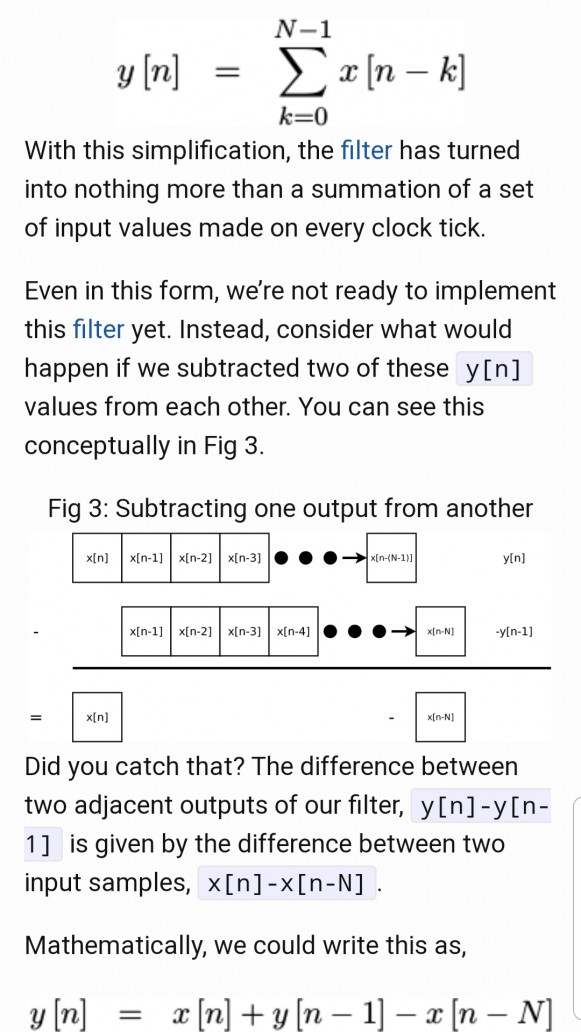
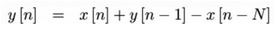
y(n) = y(n-1) + x(n)-x(n-N)
But the corrected equation is not an averager, it's what is called a "recursive running sum." A true moving averager would be, as kaz explained, the following:
y(n) = y(n-1) + [x(n)-x(n-N)]/N
whose block diagram is shown below.
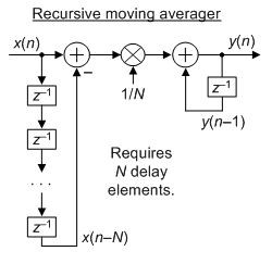
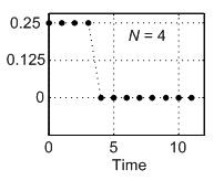
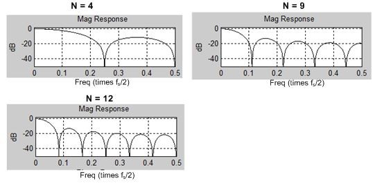
The moving averager is a recursive network but its impulse response is finite in duration, for N = 4, as shown below.
Hello Richard Lyons,
Thank you for the response. Please find the attached image. I implemented filter according to that equation. Should I divide the accumulator by N?
In the following code I'm right shifting the accumulator with bit width of N
always @(posedge i_clk)
if (i_reset)
acc <= 0;
else if (i_ce)
begin
if (diff)
acc <= acc - sub;
else
acc <= acc + sub;
end
// Clock stage four
always @(posedge i_clk)
if (i_reset)
o_result <= 0;
else if (i_ce)
o_result <= acc>>LGMEM;
endmodule
Hi Adira. The expression:
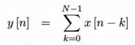
is a "nonrecursive N-sample moving summation". If you divided each y[n] output sample by N then it would be an "nonrecursive N-sample moving average." You know what the word "average" means, right? The expression:
is a "recursive N-sample moving summation." If you divided each of its y[n] output samples by N then it would be an "recursive N-sample moving average."
Sorry but I'm unable to decipher your above code. But if you want to divide a binary number by N you can do so by shifting the binary number to the right by 'log_base_2 of N' bits. For example, to divide a binary number by 8 you can do so by shifting the binary number to the right by log_base_2 of 8 = 3 bits.
Hi Richard Lyons,
I wrote algorithm based on your answer. I understand you're busy but please reply when you find time. I'm really stuck with this.
I implemented ADC on FPGA.
Sampling frequency of ADC = 1.563MHz.
Reconstructed signal frequencies range =0-3khz
ENOB achieved for 100hz signal is 7.0844 and SINAD 44.81db.
Now, I designed a moving average filter using blockram filter to filter ADC output in order toimprove the SINAD and ENOB.
Algorithm:
IW=8 //Input bit width
LGMEM = 14 // Bot width of Taps
Acc =[(IW+LGMEM):0] // accumulator
OW= [(IW+LGMEM):0]//Filter output
According to equation:
y(n)=y(n-1)+x(n)-x(n-1)
In terms of code:
Acc=Acc+sub // sub is x(n)-x(n-1)
OW=Acc>> LGMEM //accumulator divided by N
1.Is the above algorithm is correct?
2. I need Bandwidth of atleast 0-20khz. To get that I have to oversample the signal. If I take ADC oversampling frequency of 25Mhz what should be the filter sampling frequency and number of taps? Is there any way to calculate? Also, I have to achieve ENOB of atleast 12 bits.
I tried many frequency combinations. But I couldn't get the ENOB of filter output more than 7.7 .
Your terminology confuses me. I do not know what your words "Reconstructed signal frequencies range =0-3khz" or "Bandwidth of at least 0-20khz" mean.
You want to lowpass filter a discrete sequence of 8-bit binary words in order to increase the filtered signal's 'signal-to-quantization-noise ratio'. It *IS* possible to do this using the processing described by Slartibartfast's Reply. A detailed description of that processing can be found in the "Reducing ADC Quantization Noise" article at the following web site:
https://www.researchgate.net/publication/261778240...
Please note: That article describes the need to increase an ADC's sample rate. In your case I *DO NOT* think you need to increase your 1.653 MHz sample rate! So for you, I think, all you need to worry about is designing a suitable lowpass filter based on the bandwidth of your final desired lowpass filtered (and improved ENOB) signal. Now, ... at this point I do NOT know what is your desired final lowpass-filtered signal's bandwidth!
If I'm correct in understanding your problem, I do not believe a moving average filter is the right filter for you to use. I think you'll need a more traditional lowpass filter whose low-frequency passband frequency magnitude response is flat over the full frequency range of your final desired output signal's bandwidth. (Again, keep in mind that I do NOT know what is the value of that desired output signal's bandwidth.)
Assuming you need a linear-phase lowpass filter, then what I'm saying here is that you'll need to design a traditional tapped-delay line finite impulse response (FIR) filter. If you filter design is correct then the filter output's ENOB will be higher than the filter's input ENOB.
And whether or not you want to decimate your lowpass filter's output is up to you. Please carefully read the first portion of the above referenced article, and let me know if you have more questions.
Hello Richard,
Thank you, I will read that article.
Desired output signal bandwidth = 0 to 20khz or more than 20khz.
If I take ADC sampling frequency as 1.563Mhz then I can get ADC output only for input signals 0 to 3khz.
Adira. In the world of DSP the word "bandwidth" is a single number measured in Hz. For example, human speech signals are said to have a bandwidth of 4 kHz. (Notice that the "4" is a single number.)
Your words "signal bandwidth = 0 to 20khz or more than 20khz." confuse me. That is like saying, "The speed limit while driving a car in the city center is 0 to 30 miles per hour or more than 30 miles per hour." Those words just makes no sense.
Also, I don't understand your words "If I take ADC sampling frequency as 1.563Mhz then I can get ADC output only for input signals 0 to 3khz." I don't know what signal processing you are performing so those words also do not make sense to me.
Hello Rick,
You said that running sum filter is not right use. Could you please tell why it doesn't work?
I thought of designing tap delay line filter as you suggested.But it requires lot of FPGA resources. Due to lack of time , I can't really design new filter now. Could you please tell me if there's any way to get better ENOB using running sum filter?
Also, I tried many frequency combinations. But I'm not able to find suitable sampling frequency of filter and number of taps for my design. How to find filter frequency and number of taps considering ADC sampling frequency = 1.563Mhz?
Adira. The frequency magnitude responses of running sum filters do not have a flat passband. Their freq magnitude responses look like the following:
The kind of filter I think you need is a tapped-delay line lowpass FIR filter whose frequency magnitude response looks something like the following:
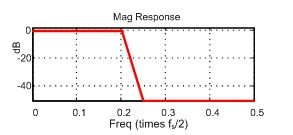
I'm afraid that I cannot help you any further because I do not know *EXACTLY* what signal processing you are performing.
Hello Rick,
I meant 0-3khz input signal to ADC. I will try to implement tap delay filter. Thank you for helping me!!!
Hi Adira. If your ADC input signal's maximum frequency is 3 kHz why is your ADC sampling rate so large (1.5 MHz)?
Hi Rick,
I implemented Tracking ADC on FPGA. I used LVDS pins as comparator. Actually, I'm oversampling but I don't understand why it's just 3khz.
Hello Rick,
I implemented running sum filter In FPGA. Input width(IW) is 8 and the log(based two) of the maximum number of averages(LGMEM) is 14. The output/accumulator bit width(OW)=IW+LGMEM. The 8 bit ADC output is filtered using this filter. The ENOB of ADC output before filtering is 5 bits and 11.75 after filtering. The accumulator bit width is 22 and every bit of accumulator is toggling but still ENOB is 11.75. What could be the reason? Does it mean the filter in inefficient?
Kindly help me to understand

Running average filter is just a low pass filter (FIR). However it can be implemented in a recursive structure that looks like IIR but is not as each new sample enters the last old sample is subtracted from accumulator cleanly.


