


How to design cic digital filter for sigma delta adc
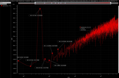
My SD ADC modulator has a sampling frequency of 1.024 MHz, an input bandwidth of 1 kHz, an oversampling ratio of 512, a single-loop second-order structure, and a 1.5-bit (3-level) quantization;
The figure above shows the FFT analysis spectrum obtained from the actual circuit simulation of my ADC,the curve of the second-order modulator exhibits a 40 dB/decade rise.
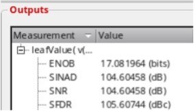
The figure above represents the results obtained from the FFT analysis.
Next, I need to design a 14-bit digital filter. The difficulty I'm facing now is how to embed the digital filter with my analog spectrum diagram. That is, how should I determine the filter specifications, passband cutoff frequency, transition band attenuation, and stopband start frequency.
My understanding is that this part also determines the output frequency, that is, the stopband start frequency is the output frequency? Then will the final output frequency of the digital filter affect the SNR? How do I balance between SNR and output frequency? And what is the connection with conversion time?

Usually all or most of that is determined by the requirements of the target application(s). In other words, what do you need it to do?
Hello
This is an ADC design applied to the internal integration of DCDC chips, used to measure voltage, current, temperature and other information, and communicate with external devices through I2C.
I have currently completed the analog part design of the ADC, and now I am designing a 14-bit digital filter.
But I don't know how to determine the specifications of my digital filter, such as the passband cutoff, the transition band range, the start frequency of the stopband, etc.
wang.jean

Hello,
So I'm gathering that you have a 3-bit value with an incoming sampling rate of Fs_in = 1.024 MHz.
You want to filter and decimate by a ratio of 512. That will give you a rate Fs = 1.024/512 = 2 kHz. Then your Nyquist zone would be DC to a little less than 1 kHz.
I've seen this done using a two-stage approach. First is a CIC filter to decimate by 256. Second is a Half-Band filter that has a pass-band response to compensate for the CIC drop-off shape and it decimates by 2. The result is a fairly flat pass-band.
Note that you can tune the delay stages in the CIC to put an attenuation zero near your cut-off frequency. It can ease the requirements of that Half-Band.
There is/was an A/D converter from Motorola that showed this method.
Here is a similar one:
https://iarjset.com/upload/2016/february-16/IARJSE...
Mark Napier
I recall also that there is a Fred Harris paper where he uses canonical half-band filters to filter and decimate. He claims that by using I2R filters, specifically the 2-path all-pass version, that they use less processing power than CIC filters.
00186486 F. Harris and B. McKnight, "OVERSAMPLED DIGITAL TO ANALOG CONVERTERS WITH VERY SMALL COMPUTATIONAL LOAD," Twenty-Fifth Asilomar Conference on Signals, Systems and Computers, vol. 1, pp. 429-433, November 4-6, 1991. Note: half-band filters.
06190159 fred harris, X. Chen and E. Venosa,"An Efficient Cascade of Half-Band Filters for Software Defined Radio Transmitters," 2011 Conference Record of the Forty Fifth Asilomar Conference on Signal, Systems and Computers (ASILOMAR), pp. 990-994, 2011.
06651203 fred harris, Elettra Venosa, Xiaofei Chen, Prafulla Kumar, and Chris Dick, "Comparison of standard low pass filter types in two-path half-band IIR filter structures,"2013 International Symposium on Signals, Circuits and Systems (ISSCS), pp. 1 - 4, 2013.
2011-6a-harris fred harris, Elettra Venosa, Xiaofei Chen, and Markku Renfors, "Cascade linear phase recursive half-band filters implement the most efficient digital down converter", Proceedings of the SDR 11 Technical Conference and Product Exposition, Wireless Innovation Forum, 2011.
"Analog Integr Circ Sig Process Cascade half-bands.pdf" fred harris, Elettra Venosa, Xiaofei Chen, and Markku Renfors, "Cascade linear phase recursive half-band filters implement the most efficient digital down converter", Analog Integr Circ Sig Process (2012) 73:531–543, Springer, 2012.
I have designed a 2-path I2R half-band in a Xilinx but that is gross over-kill in your application.
Harris talks about these filters at length in his book.
hello
Thank you for your patient reply.
This ADC is used to be integrated into a DCDC chip internally, to measure current, voltage, temperature, etc., and communicate with external devices through the I2C protocol.
I'm still in the early learning stage of digital filters.
wang.jean
Hello
In fact, I'm not sure how to determine my downsampling rate (sampling rate), or in other words, I want to get a higher SNR.
You said that a downsampling ratio of 512 is twice the bandwidth, so the output rate is 2ksps, does that mean the lower the output rate, the higher the SNR?
wang.jean
Hello,
Filtering and down-sampling will generally increase your SNR. The normal assumption is that an A/D converter introduces noise that is evenly distributed over the Nyquist zone. So if you filter out the upper 1/2 of the zone and decimate by 2 then you have gotten rid of 1/2 of the noise power. The total noise power has decreased by 1/2 so your SNR has increased by 3 dB.
Rinse and repeat.
For every 6 dB of noise gain your equivalent number of bits (ENOBs) increases by 1.
Say you filter and decimate by 512 = 2^9. So, 9 * 3 is 27 dB improvement and approximately 4.5 ENOBs gain.
Or 10*log10(512) = 27.1 dB. It is a log power relationship.
Note that in your case the noise power is *NOT* evenly distributed. The noise has been shaped to put it into the upper band. You will get more than 4.5 bits improvement. How much more I couldn't say without implementing the thing and measuring noise WRT input tones.
Also note that there is a relationship between the minimum bit widths in your data path and the achievable noise floor. Fred Harris' rule of thumb is about 5 dB per bit. So, if say your filter is 16-bit then likely your processing floor is -80 dBc.
Hope some of this is helpful,
Mark Napier


